STM32F030F4P6 breakout board
This is a tiny breakout board for STM32F030F4P6 chips. It's hand-solderable (the smallest are 0805 parts and the TSSOP-20 MCU).
It works also with other pin-compatible STM32 chips in TSSOP-20 package, e.g. STM32F042FxP6 or STM32L031FxP6.
Notice: I'm selling some of the breakouts on Tindie; or you can just order PCBs from pcbs.io or OSH park.
Description
These very cute MCUs are hand-solderable but still very small, and have a built-in UART bootloader in ROM. They have 16kB (F030) or 32kB (the "F6" ones) of flash and 4kB (F030) or 6kB (the "F6" ones) of SRAM. The usual capabilities (timers, I2C, SPI) are of course present as well. For a detailed list of capabilities, see the F030 datasheet.
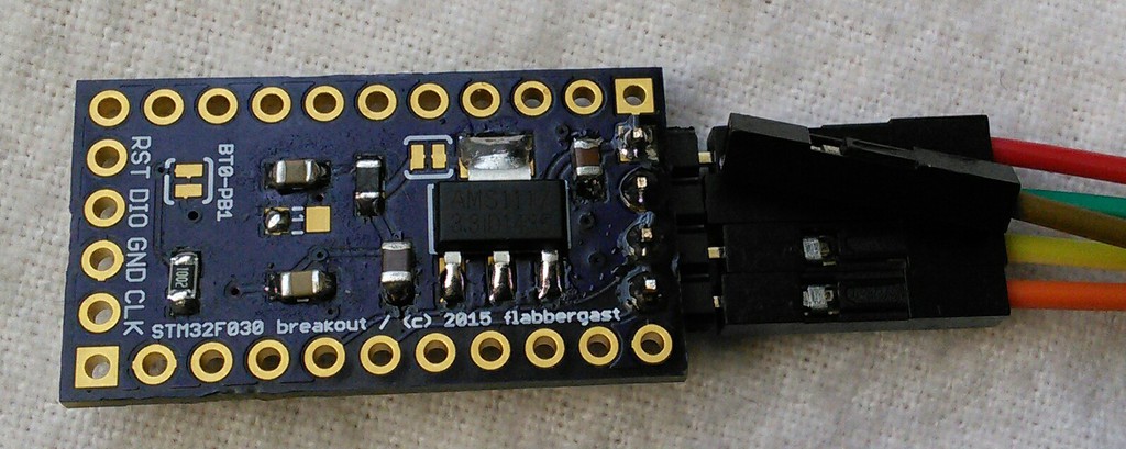
The board is made to be somewhat analogue-friendly: the analogue voltage source (VDDA) is connected to the main voltage regulator output through a ferrite bead, and there's an extra 1uF capacitor on VDDA as well.
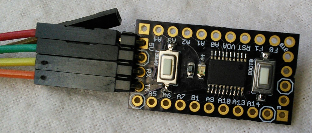
This board itself breaks out all the MCU's pins on the longer sides; UART pins on one of shorter sides (there are 4 pins soldered to these) and the SWD debug pins on the other shorter side, for an easy debugging access. Furthermore there is one onboard (yellow) LED, and apart from the RESET button there is also a button hooked to the BOOT0 pin.
This means that to program the chip simply hold the BOOT0 while pressing the RESET (or powering up the chip), and it enters the UART bootloader. You can then upload the firmware via the UART interface (usually using an USB-to-serial breakout). This is a hardware feature, so it always works, even if the actual firmware doesn't cooperate.
Hardware
The design is open source, here is the schematic and eagle files. The gerbers have been uploaded both to OSH Park and pcbs.io. (The latter give me a tiny discount if you order through them.)
The pins are marked on the silkscreen, ground pins have an octagon around them and power pins are square.
The two solder jumpers are connected by trace by default, which needs to be cut if you want to disconnect them initially.
- the BT0-PB1 connects the BOOT0 pin with PB1 pin, meaning that you can detect the bootloader button state also on PB1.
- the other solder jumper (close to the regulator) connects the regulator output with the 3V3 net. It's there for the case when you have a regulated 3.3V available somewhere else, and it is routed to the 3.3V pin.
If you are soldering this yourself, you'll need:
-
STM32F030FxP6 MCU (these can be had el-cheapo from aliexpress, if you trust the Chinese enough)
-
AMS1117-3.3V voltage regulator (also see aliexpress)
-
two pushbuttons (e.g. from ebay, visual match is sufficient to yield the correct part)
-
some 0805 parts:
- LED
- 1kOhm resistor (for the LED, you can adjust this as needed)
- 10kOhm resistor (pull-down for BOOT0, also adjustable 10-50 kOhm range should work)
- 2x 0.1uF filtering capacitors
- 10uF and 22uF capacitors: these are stabilising caps for the AMS1117, and these are the lowest recommended values
- 1x 1uF capacitor and 1x ferrite bead (220Ohm@100MHZ) - these are optional (if you want a cleaner analogue supply), you can just bridge the ferrite footprint instead
Firmware
A test firmware is available here. It runs a serial echo on USART1 (so if you connect an UART to the pins on the "short UART" side of the board, it'll send back what it gets) and blinks the LED. Pressing the bootloader button will print "hello, world" over the serial.
Making firmware is up to you; I've personally used both ChibiOS and libopencm3 to create firmware for this board.
USART bootloader
For programming a firmware onto the board, I use stm32flash. Connect the "short UART" side to a serial converter (e.g. one of the plethora FTDI, or CP2102, or CH340G USB-to-serial converters; just make sure that the signals are at 3.3V levels) and provide some power to the board. Hold the BOOT0 button and press RESET. This will put the MCU into the bootloader mode. Verify that stm32flash can talk to the board:
stm32flash /dev/<serial_dev>
where <serial_dev> your USB-to-serial device, usually ttyUSB0 or
ttyACM0 on Linux, or something like tty.usbserial-DJ005L on macOS.
Flashing firmware.bin is then done with
stm32flash -e 255 -v -w firmware.bin /dev/<serial_dev>
SWD debugging
Debugging is possible via SWD, whose two pins (SWCLK and SWDIO) are
brought out to the "other" short side. Broadly speaking, debugging will
require a hardware SWD debugger (e.g. a STLink V2 clone (ebay, ali) or a
jLink clone (ebay, ali), or a Black Magic Probe), some means for the
PC to talk to it (usually stlink for STLink V2, openocd for jLink,
and nothing special for BMP), and debugger software (usually gdb,
distributed along with gcc for ARMs, called arm-none-eabi-gdb).
The software setup is usually somewhat fiddly and system-dependent;
here's a short rundown with STLink V2 and linux/macOS: get Texane's
stlink software somehow. Connect the hardware. Run st-link in one
window. Compile your firmware into firmware.elf. Run debugger with
arm-none-eabi-gdb firmware.elf. In the debugger command line, use
target extended-remote :4242 to connect to the st-link program.
Then the usual debugging commands should work, e.g. load downloads
the firmware into the MCU, run will run it, etc...
It is probably convenient to use some gdb front-end, I prefer cgdb.