A 'paperPCB' amplifier with LM386
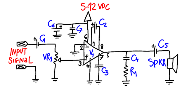
I wanted to make a simple amplifier (essentially for use with Arduino), a little googling showed that one of the simplest ones uses LM386 operational amplifier chip. There are very many slightly different schematics to be found on how to go about using LM386. In the end, I used the one below, a combination of what I found and which parts I had on hand ;)
One reason I like it drawn this way is that it is modular: it shows various relatively independent parts of the circuit, and also makes it easy to see which adjustments can one make:
- C6 (470uF) and C7 (100nF) are for stabilising the power source (I actually didn't include C7 in my PaperPCB, since that one is for filtering IC generated noise, and I don't intend to use it that way).
- C2 (up to 10uF) is gain: without any cap there, the gain of the amp should be 20, with 10uF cap it should be 200 (according to the LM386 datasheet).
- VR1 (10kOhm or 100kOhm) is for regulating volume. Logarithmic potentiometer should make sense, but I didn't have one, so I just used a linear one.
- C3 (100nF) is bypass (should reduce noise; see datasheet).
- C4 (100nF) and R1 (10Ohm) constitute an RC-filter to smoothen the output.
- C1 (10uF) and C5 (470uF).
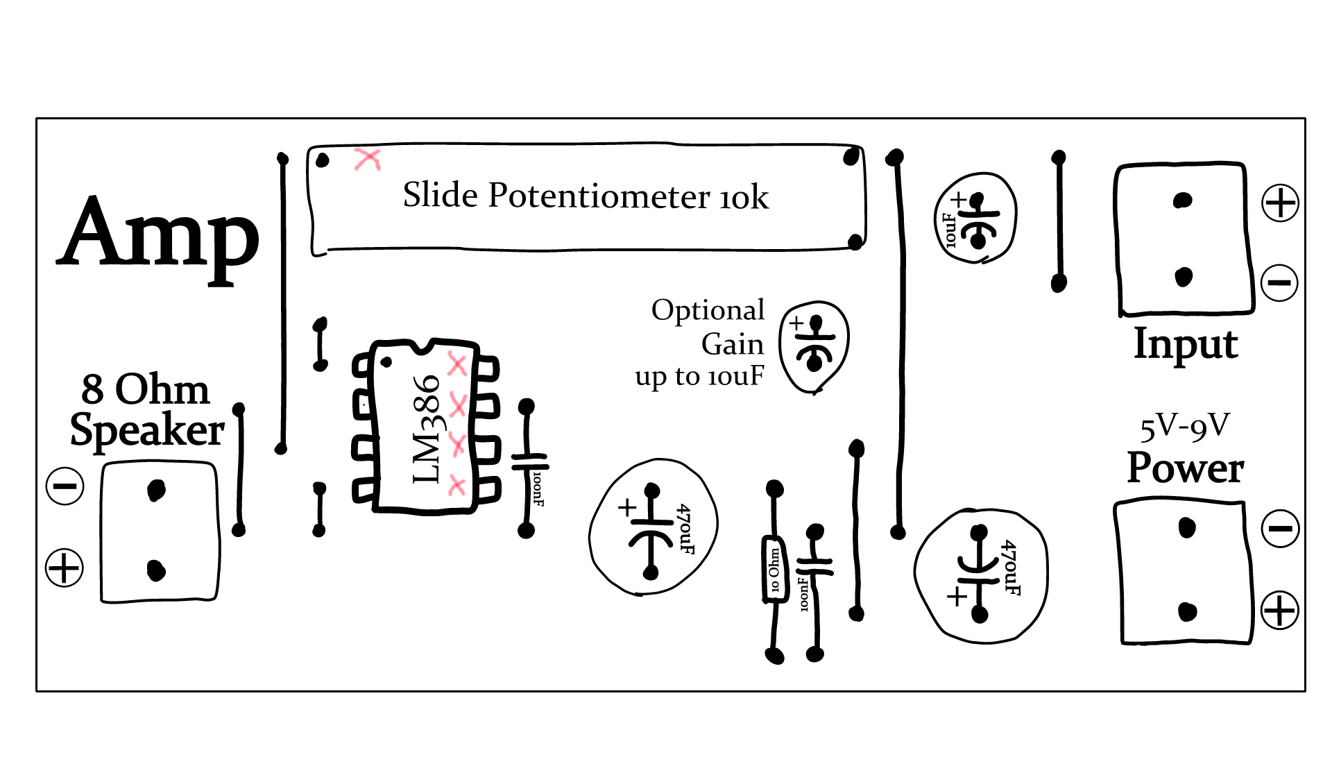
I like the PaperPCB designs of Wolfgang Spahn very much, so I made a similar thing myself: drawn an image to be printed, decorated, cropped and glued onto a piece of stripboard. Then the parts are soldered into the indicated positions. The image I created is below --- you can download it and print it yourself (the proper scaling is included in the image file, so just select "Zoom: 100%" or equivalent when printing).
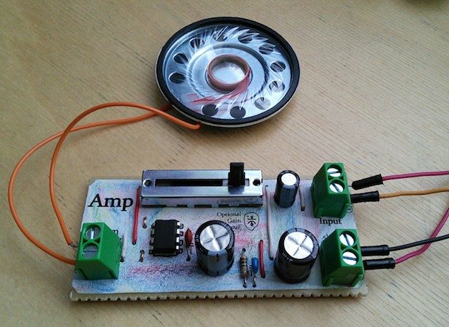
The final thing:


