X-A4U stick
Notice: I have some leftover PCBs, selling on Tindie.
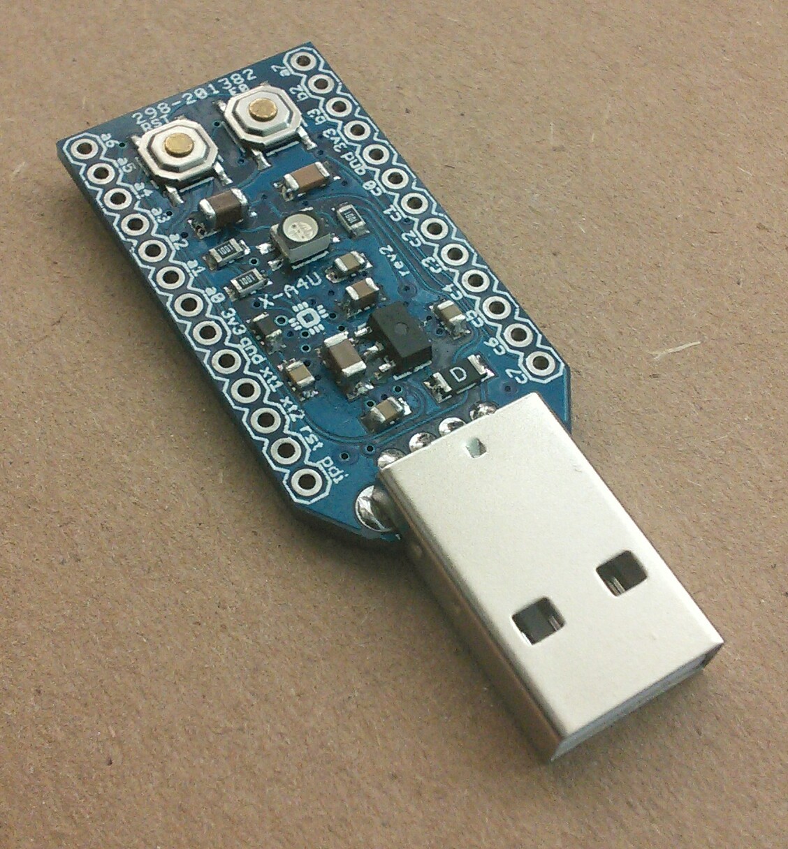
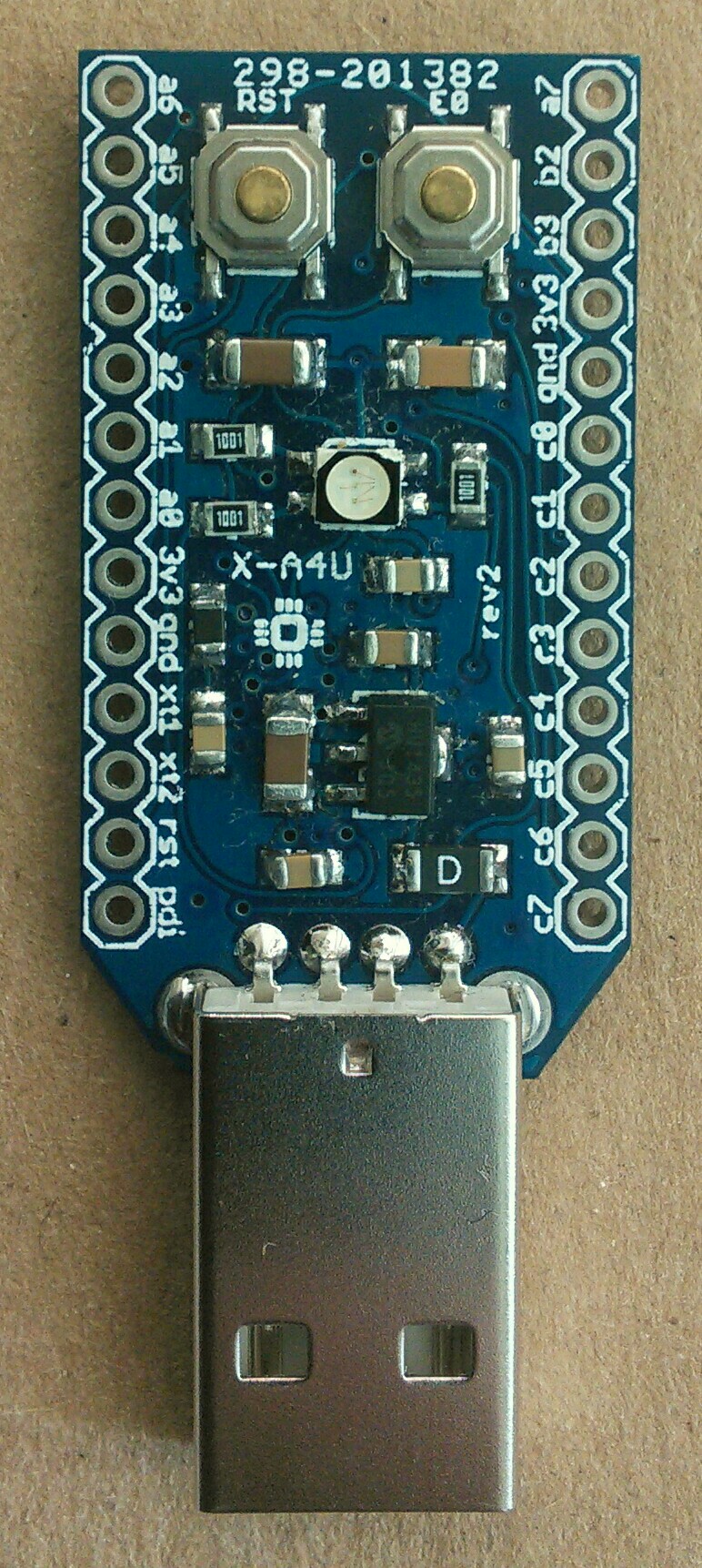
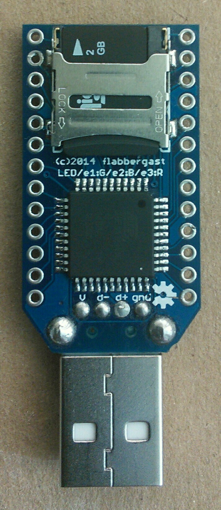
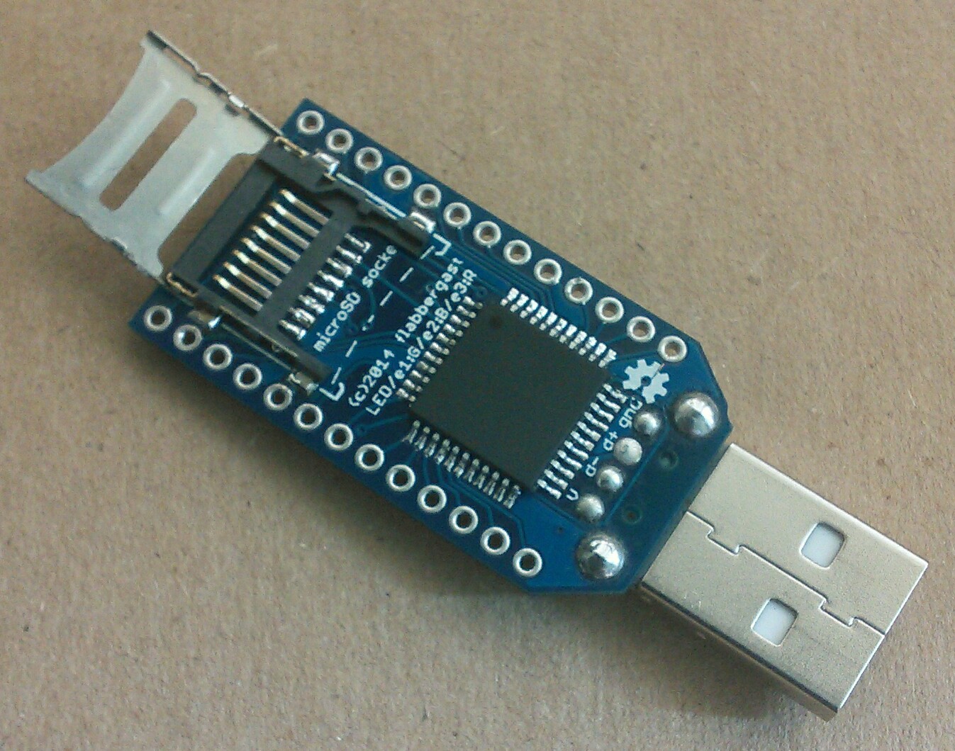
A small programmable USB stick, with ATMEL's ATxmega128A4U on board. It's also got a microSD socket, RGB led and two buttons (one of which is RESET).
The possible usages of this stick that I had in mind when designing it were:
- Use microSD as mass storage, but encrypting the data before writing. An alpha version of firmware is here: enstix. Note that it's relatively slow (I was getting about 130kB/sec for reading).
- Use the stick to act as keyboard (+mouse), reading what should be "pressed" from microSD - much like the Rubber Ducky, with an addition of a mouse.
- Use RGB led for a mood light (sample firmware linked below).
It is designed to be solderable by hand - I soldered it with just a regular soldering iron (and a lot of liquid flux - it works like magic).
Downloads/resources
- EAGLE files are in my public repo - it's Open Hardware.
- Schematic png
- Test firmwares
Description
- ATxmega128A4U: actually any -A4U xmega would work. Here's datasheet and manual.
- MicroSD socket (datasheets here and here2). I used cheap hinged sockets from ebay, since I couldn't find push-push sockets which would fit in and be cheaply sourceable.
- One general pushbutton and RESET pushbutton.
- RGB LED ("standard" SMT 1210).
- A reasonable (?) amount of xmega's pins routed out to through-hole pads with standard spacing - so potentially usable on a breadboard, or with a homemade "shields" from a piece of protoboard. The PDI programming interface and crystal/oscillator pins are also brought out.
- The 3.3V regulator is 250mA MCP1703.
- The smallest SMT parts are 0805, and some are 1210.
- The xmega is bootloaded with ATMEL's DFU bootloader.
Usage notes
Software/firmware side
The atxmega is bootloaded with ATMEL's DFU bootloader, which is entered by pressing the E0 button during power-up or reset. So to program the stick, enter the bootloader mode, the stick should enumerate as ATMEL DFU device (this probably needs a driver on Windows - I haven't tested it yet), and then either use ATMEL's FLIP utility, or the open source dfu-programmer.
Probably the easiest way to write firmware for this stick is to use avr-gcc (windowed people can get it as WinAVR distribution). Alternatively ATMEL Studio can be also used on Windows. Of course, instead of C or C++, you can go full hardcode with assembler.
For programming USB interfaces (i.e. to make the stick pretend it's a keyboard, mouse, MIDI device, etc...), Dean Camera's LUFA is incredibly handy. For some examples directly for this stick, see the Test firmwares linked also in the Downloads section.
The stick is now supported in Arduino using xmega-arduino add-on - still alpha quality, and with some caveats (e.g. only USB Serial, no Keyboard or Mouse yet, no autoreset), but nevertheless it is useful for some quick testing.
Hardware side
The button is wired to PE0, the RGB LED to PE1 (green), PE2 (red) and PE3 (blue). (Note there's a mistake on the silkscreen, red and blue are switched.)
The through-hole pads are (as marked on the board):
3V3andGND(one pair on both sides),PR0andPR1(for crystal),PDIandRESET(for PDI programming),- all 8 pins of
PORTC(mostly digital functions), - all 8 pins of
PORTA(mostly analog functions) and PB2andPB3(because that's whereDAC0andDAC1are).
The voltage regulator is rated to 250mA, same as the PTC fuse. However it's SOT-89 package, so the heat dissipation provided by the package might not be sufficient when one gets close to the rating.
The analog supply voltage pin (AVCC) is connected to the supply through a ferrite bead, as per ATMEL's recommendation, so the analog output (DAC0/1) and analog input should be relatively clean - but I don't have an oscilloscope to verify this.
Pinout diagram
                    /-------------\
 [A6 16]      ADC6  | A6       A7 | ADC7            [17 A7]
 [A5 15]      ADC5  | A5       B2 | ADC10 DAC0      [8]
 [A4 14]      ADC4  | A4       B3 | ADC11 DAC1      [9]
 [A3 13]      ADC3  | A3      3V3 |
 [A2 12]      ADC2  | A2      GND |
 [A1 11]      ADC1  | A1       C0 | SDA       OC0A  [0]
 [A0 10] AREF ADC0  | A0       C1 | SCL  XCK0 OC0B  [1]
                    | 3V3      C2 |      RXD0 OC0C  [2]
                    | GND      C3 |      TXD0 OC0D  [3]
          PR1 TOSC1 | XT1      C4 | /SS       OC1A  [4]
          PR0 TOSC2 | XT2      C5 | MOSI XCK1 OC1B  [5]
                    | RST      C6 | MISO RXD1 OC1C  [6]
                    | PDI      C7 | SCK  TXD1 OC1D  [7]
                    \             /
                     \--- USB ---/

  E0/button  E1/green  E2/red  E3/blue  B0/cardselect
    [18]       [19]      [20]    [21]     [22]
        (bracketed are Arduino pin numbers)
Pages below refer to the xmega AU manual.
ADCnare analog-to-digital converters, page 339. Analog comparator also available on these pins, page 337.AREF: external voltage reference for analog functions, pages 343 and
DACn: digital-to-analog converter, page 367.SDAandSCL: Two-wire aka I2C interface, page 251. This one'sTWICfor avr-gcc.XCKn.RXDnandTXDn: serial interfaces, page 280./SS,MOSI,MISO,SCK: SPI interface, page 273. This one'sSPICfor avr-gcc.OCnx: 16bit timers/counters, page 162. In avr-gcc, useTCCn.PRnare the actual pin names for these two pins. See pages 85-86 and 90 for diagrams for the external crystal, and generally about clock selection possibilities.- The numbers in brackets are Arduino digital pin numbers, the
Axare Arduino analog pin labels - both using xmega-arduino add-on.
Technical points
-
The microSD SPI interface is also to
PORTC, with the exception of the chip select pin. This means that/SSpin fromPORTCcan be used for any external SPI chip, and also that the xmega can act as SPI slave. One warning though: when using the hardware SPI (e.g. for microSD), the/SSpin onPORTC(namelyPC4) should not be an input andLOW- this hangs the usual SPI code. So, even thoughPC4is not used for talking to microSD, it needs to be an output, or tiedHIGH. -
In the current revision there's no way to bypass the voltage regulator (and power the board by wiring regulated 3.3V to one of the pads), so the board is not really suitable for very low power applications. It's really meant to be used as a USB stick. (For low power applications with ATxmega128A4U, or when more pins are needed, I recommend Batsocks' boards or MattairTech's breakout.)
-
If you're interested in playing with the more powerful ATxmega128A3U, there's a similar stick by matrixstorm: AVR stick.
Soldering instructions
First, some general SMT soldering info that I found useful:
- Use liquid flux. It works like magic!
- Get a thin solder (I like 0.5mm diameter the best).
- Watch some youtube videos about SMT soldering.
- Short recap from youtube videos that I've seen: when soldering pretty much any part, first apply a bit of solder to one of the pads (a corner one is the best), position the part, and solder that one bit. For me, the part usually ends up not positioned entirely correctly, so just heat that pad again, and shift the part until it sits properly. Then (and only then!) solder the rest of the pads.
- For the IC and microSD socket, "drag soldering" worked very well for me: this means that after positioning the part and anchoring one pad, apply liquid flux to the row of pins/pads that is going to be soldered, pick up a bit of solder onto the iron and drag the iron across the pins.
Now, for this stick in particular: The parts are mostly not too close to each other, so it does not really matter in what order you solder them. Here's the way I do it:
- First the IC, then microSD socket. That does the bottom side of the PCB. I do it first because with no parts on top, the PCB sits nicely flat on the desk. The dot in one the corners of ATxmega should match the dot on the PCB.
- On the top side, I start with the voltage regulator, then the caps around it (1206 22uF capacitor and 0805 1uF capacitor - this is just "above" the voltage regulator when the USB connector points downwards). The caps are not polarized (i.e. it doesn't matter which way they're put in).
- Then some more small parts: the four 0805 0.1uF capacitors, arranged in a skewed rectangle around the regulator. I think the atxmega would work without them, but I haven't actually tried. Strongly recommended by ATMEL.
- The 0805 ferrite bead - this one is almost black compared to the caps, so see the pics where is it supposed to be. Also not polarized. This is also not strictly necessary (although recommended by ATMEL): it's there to get a cleaner supply for the analog functions of the xmega. Most of the atxmega128A4U breakouts just don't have the bead in there. So, if you like, you can just bridge the two pads instead of soldering the bead in.
- The 1206 PTC fuse (with the "D"). Goes close to the USB connector. Not polarized. Also can be just bridged if needed - in my experience the computer's fuses kick in much faster than this kind of fuse reacts if something goes wrong (i.e. a short circuit).
- The 1210 RGB LED. This one is polarized. It's not very visible on the silkscreen, but the upper-left corner (the closest one to the top of the letter "B" from "RGB") of the marked rectangle is slanted. This needs to match with the "cut" corner of the LED.
- The three 0805 1kR resistors. These go around the LED. Not polarized.
- The remaining two 1210 capacitors, 10uF and 0.1uF. Their position is marked on the silkscreen. Not polarized. You may get away with not soldering those - the 0.1uF one is to filter the IC noise from the microSD circuitry and the 10uF one to smooth out the power to it. So a microSD may work without those. Haven't tried.
- The two buttons.
- Finally, the USB socket. It should go in from the top side, and a bit of force may be required to press it all the way to the PCB.
- That's it!
If you make something interesting with the stick, I'd like to hear about it!
BOM
| N | name | value | package |
|---|---|---|---|
| 1 | blue 1.6mm thick PCB | ||
| 1 | ATxmega128A4U | TQFP-44 | |
| 1 | male USB A THT connector | ||
| 2 | SMT pushbutton | ||
| 1 | microSD socket | ||
| 1 | RGB LED (common anode) | 1210 | |
| 1 | PTC fuse | 250mA | 1206 |
| 1 | MCP1703-3.3 (250mA) | SOT-89 | |
| 3 | resistor | 1kR | 0805 |
| 4 | ceramic capacitor (X7R) | 0.1uF | 0805 |
| 1 | ceramic capacitor (X7R) | 0.1uF | 1206 |
| 1 | ceramic capacitor (X7R) | 1uF | 0805 |
| 1 | ceramic capacitor (X7R) | 10uF | 1206 |
| 1 | ceramic capacitor (X7R) | 22uF | 1206 |
| 1 | ferrite bead | 220R@100MHz | 0805 |


