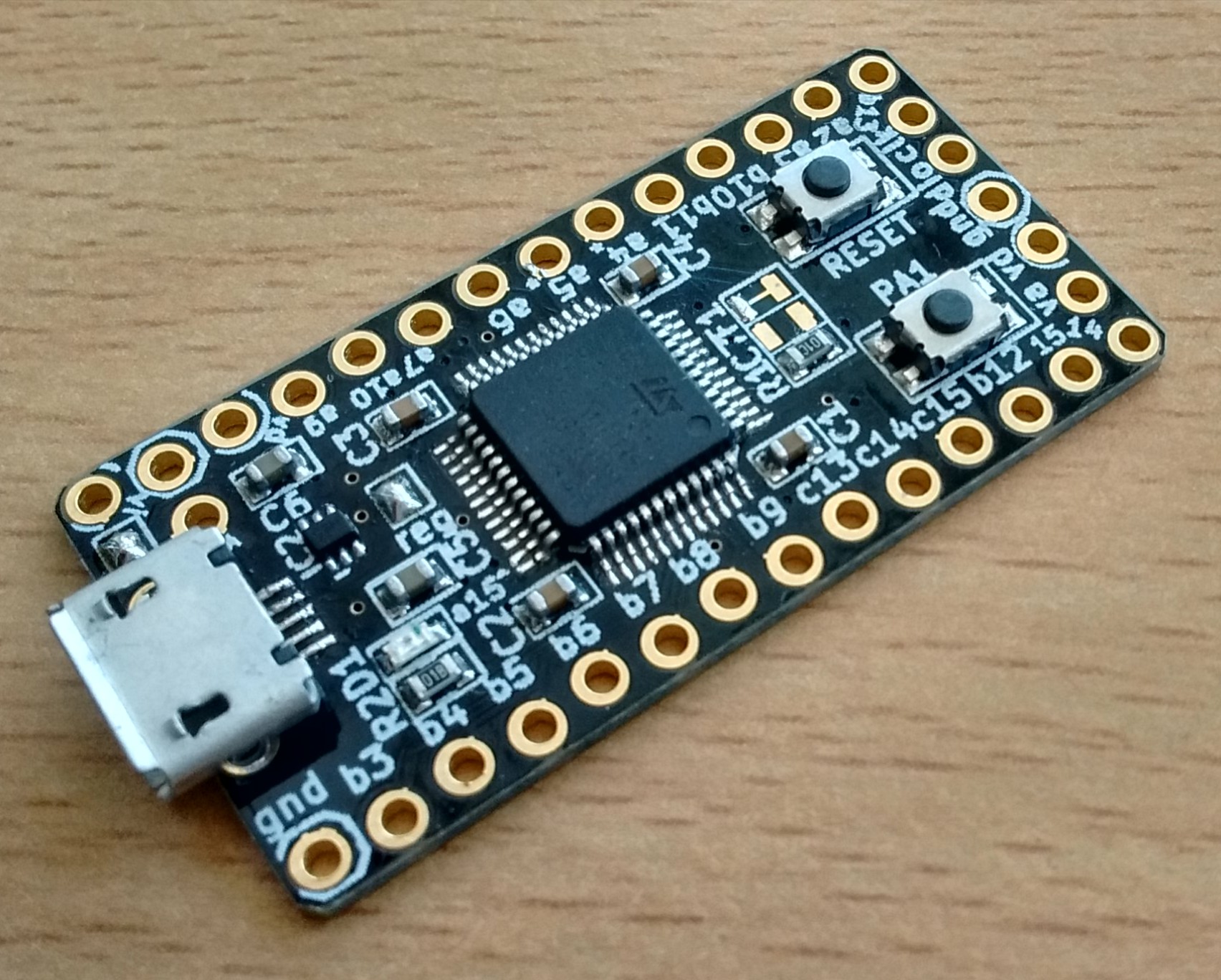
the bat board
This is a (hand--solderable) breakout board for STM32 ARM MCUs in LQFP-48 package. I mainly had in mind STM32L052CxTx (for low power applications) and STM32F072CxTx (for USB applications). From rev3 up, it can also support the ubiquitous STM32F103CxT6. The design files and documentation are freely available (here). Tested with L052, F072 and F103.
(Consider these pages as archives: not actively developed.)
Board features
It's a pretty minimal breakout board:
- USB
- most pins broken out
- reset pushbutton
- another pushbutton on PA1 (also connected to BOOT0 via a solder jumper)
- one LED (on PA15)
- Teensy sized
- hand--solderable (well, 0603 parts)
- power options: VBUS connected to VIN through a solder jumper (when disconnected, one can mount a battery charger in between); the regulator is connected to VDD through a solder jumper (so it can be turned off completely when the board is powered directly to VDD, either from a battery or an already regulated supply)
- ultra low power NCV8170 3V3 150mA regulator (quiescent current 0.5uA, 2uA ground current for <= 0.5mA output)
- optional ferrite on the analogue supply
- optional high speed external crystal (needed for USB on Cortex M3 and higher, but not for Cortex M0)
- optional pullup on the USB D+ line (not needed for the Cortex M0 chips, but it is needed for USB on Cortex M3 and higher)
The point of this board is to have a teensy-sized breakout for USB capable STM32 chips, suitable for very low power applications (e.g. a battery powered sensor).
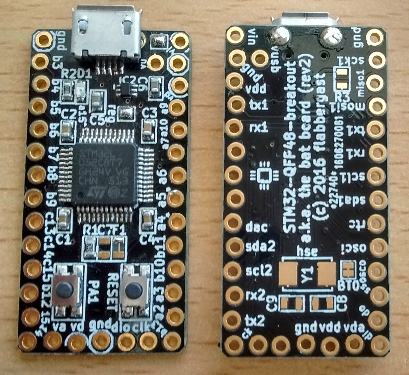
UPDATE: I've made an "add-on" board for this breakout, namely to turn it into a SerPlus board: USB-CDC-input and standard 6 pin UART output, used either as a basic USB-to-serial converter, or as an "telnet-enhanced" convenient communicator with e.g. Jeenode Zero. It's semi--documented in this post.
UPDATE2: I have now tested the power consumption with L052, running mecrisp stellaris, with jcw's code (modifications here). With voltage regulator supplied with 5V, the board takes 4.5uA in stop mode. That's very nice, and it also means that the regular really consumes only about 1.5-2uA of current. Note that stop mode retains RAM contents, so after wakeup the firmware continues running from where is left off; but to get to this low consumption it needs to run 2.1MHz on MSI oscillator only.
Miscellaneous
I tested the boards with STM32F072CBT6 (128Kbytes of flash, 16Kbytes of RAM, built-in DFU bootloader), with STM32L052C8T7 (64Kbytes of flash, 16Kbytes of RAM, very low power states) and with the ubiquitous STM32F103C8T6. The L052 and F103 only have an USART bootloader built-in (for more about this see below).
I have no plans at the moment to support these through Arduino (although if there will be a reasonably mature STM32 add-on, then it should be simple to add these).
JCW at Jeelabs also has an L052 board, the Jeenode Zero, for sale here. This one has a RFM69CW radio on board, as well as a socket for a CR2032 coin cell. Yummy! No USB though. It runs forth!
Forth is also supported on the bat boards; on L052 only through USART so far, but I've modified JCW's serial-over-USB to run on F072 as well. Sources and a flashable binary is here. I will update this page with links to code when it is ready.
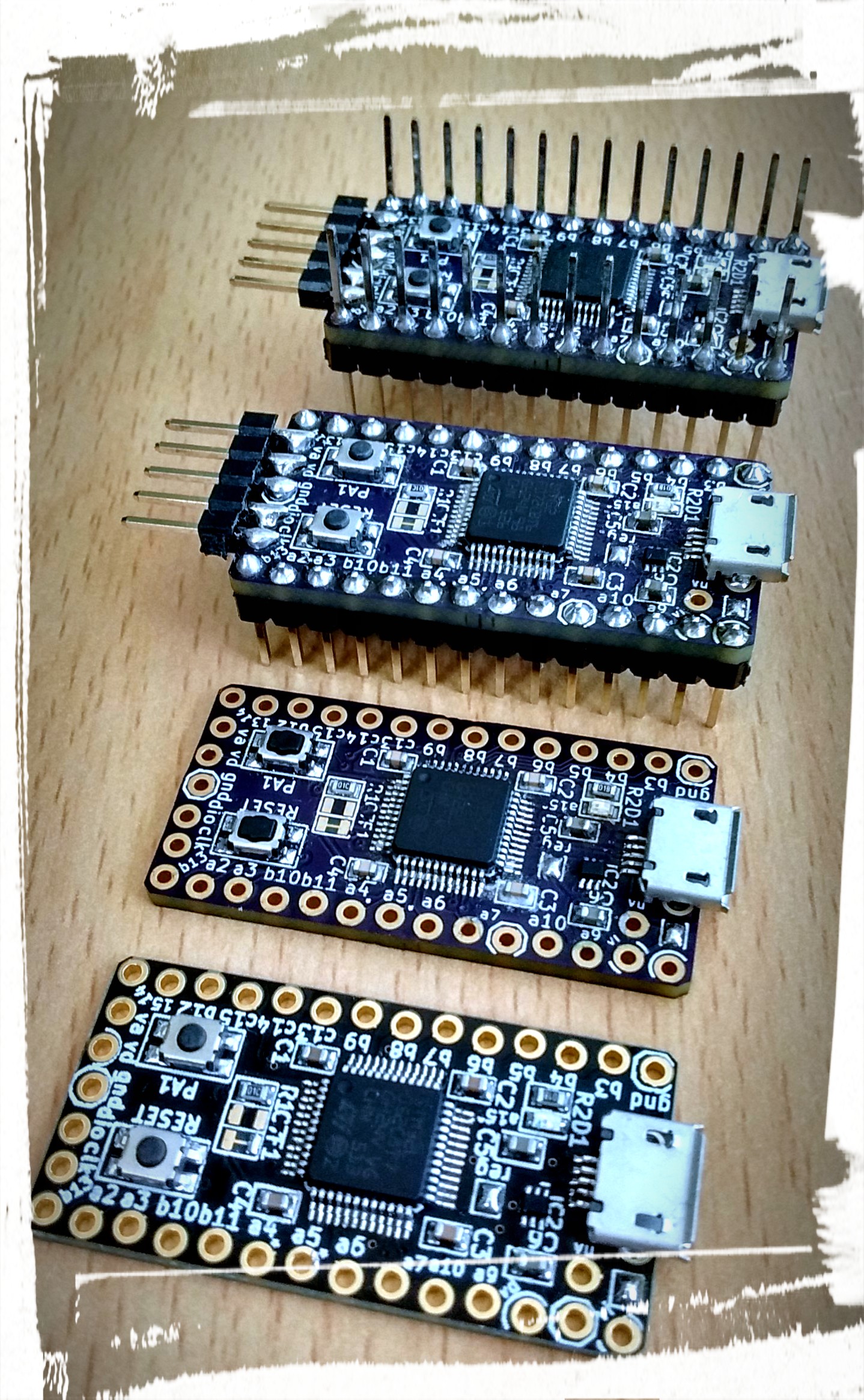
(Three rev1 (top) and a current rev2 (bottom).)
MCU-specific notes
STM32F072CxTx
These are the easiest to use with this board. None of the "optional" components are required, and no external hardware is needed even initially, thanks to the DFU bootloader.
STM32L052CxTx
These are the main target of this board, for low-power prototyping and sensors. None of the "optional" components are required.
Because these don't have DFU bootloader built in (more on this below), either an UART (USB-to-serial board or something like that) with 3.3V logic level, or a SWD debugger (JLink, ST Link V2, Black Magic Probe, ...) is required to get started after soldering the board.
STM32F103CxTx
These are used in a variety of STM32 boards available (including the $2 "blue pill" boards on ebay from China). If one wants to use USB (and clock them higher than 48MHz), the external high speed crystal is needed (there's a footprint for this on the bottom side of the board, plus the accompanying capacitors). Furthermore, this chip does not have an internal pull-up on the D+ line (to signal the computer that an USB device has appeared). Hence this requires an external circuitry (usually implemented with a transistor and some passives); this board offers one of the simplest solutions, namely a footprint for a resistor from D+ to a GPIO pin (PB7).
Finally, the pin used for LED on this board (PA15), is assigned to one of the JTAG functions by default (this causes the LED to light up slightly by default; e.g. when in the bootloader mode). Hence, to use the LED, one should disable JTAG (debugging is still possible through SWD). This is done by enabling RCC_AFIO clock, and setting the appropriate SWJ_CFG bits in the AFIO_MAPR register. If the desired outcome is to disable JTAG, leave SWD enabled and AFIO_MAPR is in its default state, this can be achieved with "AFIO_MAPR |= (1<<25);" in C.
Bootloaders
When the second onboard button is connected to the BOOT0 pin on the chip (it is by default), holding this button while resetting (or powering up) the board will force the MCU to enter the built-in bootloader. On both F072 and L052 there is an USART bootloader, listening on PA9(TX) and PA10(RX) - the two pins right next to the power pins on the 'top' of the board (and usually some more options, like the other USART, I2C or SPI). Loading firmware using this bootloader (e.g. using stm32flash) will always work, regardless of the current firmware.
Another way to load firmware onto the board is to use the SWD pins. These are on the short side opposite to USB, and of course they can be used for debugging as well.
Finally, the F072 MCU also has a USB DFU bootloader built in, meaning that pressing the BOOT pin and resetting the board, while connected to USB will activate this DFU bootloader. Then the firmware can be uploaded e.g. with dfu-util.
The L052 however does not have a DFU bootloader built in. So I modified the bootloader used by the BMP folks to run on L052 as well. It occupies the first 8Kbytes of flash, and hence expects the firmware to begin at address 0x8002000. (One of the first instructions in the firmware should be to relocate the vector table to this address.) This bootloader is entered by connecting PB3 to GND (so e.g. by putting a jumper across the two pins at the edge of the board) when resetting/powering up. See Usage/Examples for downloads. Of course to put it on a fresh board, you'll need to use the USART bootloader (with some USB-to-serial board, there are oh so many on ebay for $1), or load the firmware through SWD (with some SWD debugger, e.g. STlink, there are oh so many on ebay for $3).
Usage/Examples
A few examples of C code using libopencm3 are in my public repo. The sources show the code differences needed for different MCUs, it's done using #ifs in the sources.
(In particular, using L052 with the bootloader supplied below requires relocating the vector table, which is done like this.)
Precompiled test firmwares
Some of the above (including the L052 bootloader) can be downloaded here, compiled into a binary firmware.
- button-blink: periodically blinks the LED, keeping the button pressed stretches the period: for F072 | for L052 with DFU bootloader
- CDC-ACM demo: the board presents itself as a serial device; after connecting to it it simply echoes what it receives and toggled the LED when it sends an USB packet (usually after each typed character): for F072 | for L052 without DFU bootloader | for L052 loading thru DFU | for L052 including DFU bootloader for loading at 0x8000000
- the DFU bootloader for L052 is here
A few comments about uploading:
Using stm32flash
Install it however you like (usually download and compile). After entering the bootloader (see above), check that it can talk to the bootloader by
stm32flash /dev/tty.usbserial-DJ005L
(replace /dev/tty.usbserial-DJ005L with the appropriate handle for your serial port; on linux it's usually /dev/ttyACM0 or /dev/ttyUSB0. To flash, I use
stm32flash -e 255 -v -w firmware.bin /dev/tty.usbserial-DJ005L
It tends to fail for me without an erase first, hence the -e 255 parameter.
Using dfu-util
Again, get the program somehow (e.g. homebrew on Mac OS X) and put the board into DFU mode (see above). To check that the program can see the board, use dfu-util -l. This may require extra permissions on linux (so either mess with udev rules, or use sudo). Then to flash, I use
dfu-util -a 0 -s 0x08000000 -D firmware.bin
on F072s, and
dfu-util -a 0 -s 0x08002000 -D firmware.bin
on L052 with the bootloader described above.
On Mac OS X High Sierra, I had to add -d 0483:df11 as a parameter to dfu-util, because for some reason there's an ever present "Runtime" DFU device. (I didn't have to do this on Yosemite.)
Debugging with openocd and gdb
This usually quite fiddly and setup-dependent, so only briefly. Get openocd. The openocd config file that works for me (for the L052 boards) is this:
    source [find interface/jlink.cfg]
    transport select swd
    set WORKAREASIZE 0x2000
    # reset_config none separate
    set CHIPNAME STM32L052C8
    source [find target/stm32l0.cfg]
    $_TARGETNAME configure -event gdb-attach {
       echo "Halting Target"
       reset init
    }
I use a jlink clone; for STlink V2 change jlink to stlink-v2 and swd to hla_swd. For F072 boards, change CHIPNAME, stm32f0.cfg. You can also play with WORKAREASIZE (0x4000?). Run openocd as openocd -f config_file.cfg. Connecting to it from arm-none-eabi-gdb is as usual, telling gdb target extended-remote :3333. The usual commands should then work, e.g. run, load (if you passed an elf of the firmware to gdb), etc... I personally like using something on top of the bare gdb, to make the navigation around the sources easier. I use cgdb.
If you have STlink V2, instead of openocd you can also use st-util. Connect to it from arm-none-eabi-gdb with target extended-remote :4242.
For the record, the command to read flash from the MCU to disk (e.g. for a backup of a running firmware) is dump ihex memory FILE 0x8000000 0x8008000, where ihex can be also binary and the last number is 0x8000000 plus flash size (in hex here).
Hardware
The board was designed in kicad; the board files are here. You can order the boards from OSH Park, or from pcbs.io (they give me a tiny discount when you order from them). Or get a board from me: Tindie or email ;)
      gnd          USB         vin
  sck1/b3                 vbus gnd
 miso1/b4                      3v3
 mosi1/b5                      a9/tx1
   tx1/b6                      a10/rx1
   rx1/b7                      a7
  scl1/b8                      a6
  sda1/b9                      a5
  rtc/c13                      a4/dac
osc_i/c14                      b11/sda2
osc_o/c15                      b10/scl2
  ss2/b12                      a3/rx2
mosi2/b15                      a2/tx2
miso2/b14                      b13/sck2
          vdda 3v3 gnd dio clk
An ascii version of the pinout (rev2 and up). The alternate functions are those that are marked on the bottom silkscreen on the PCB, but naturally the MCU has usually more functions on those pins than just the one I marked.
Schematic

BOM
   IC1 STM32L052C8T7     LQFP-48
   IC2 NCV8170           SOT-563
   J1  USB_mini_micro_B  with 2 through holes
   C6  2.2uF             0603
   C5  2.2uF             0603
   C1  0.1uF             0603
   C2  0.1uF             0603
   C4  0.1uF             0603
   C3  0.1uF             0603
   R1  10kR              0603
   R2  1kR               0603
   S2  PA1               4x3mm
   S1  RESET             4x3mm
   D1  LED               0603
   F1  FERRITE-BEAD      0603  optional, 220Ohm@100MHz
   C7  1uF               0603  optional
   Y1  CRYSTAL                 optional
   C8  18pF              0603  optional
   C9  18pF              0603  optional
   R3  1.5kR             0603  optional
The pushbuttons that work are for instance these on farnell, the crystal has this footprint. The micro USB connector has 2 through holes.
Note: if you are fitting the ferrite bead, you need to cut the trace in its footprint before soldering it!
Note: the values of the passives are to some extent flexible, have a look at the schematic. For instance:
- C5, C6 are there to stabilise the regulator and C5 also to smooth out any power drain spikes by the MCU or other stuff supplied by the board's 3V3. The NCV8170 is stable already with 1uF caps.
- R1 is the pulldown on the BOOT0 pin (so 10-50kOhm range is probably OK).
- R2 is current limiting resistor for the LED, so go with whatever your LED allows (and fiddle with the brightness).
- C1-C4 are filtering caps for the MCU. It is quite possible that the MCU will run reasonably stably even without those, especially on lower clock speeds.
Revisions
- rev1 -> rev2: Added the option for a pullup resistor on D+ and solder jumper to disconnect the button from BOOT0. Modified pinout to be power compatible with Teensy 3.x, so that power/charger boards for teensy can be used with here.
- rev2 -> rev3: Connected PB2 (BOOT1 pin) to ground. This is only for the M3 and higher MCUs to have a predictable bootloader behaviour. No effect for the M0 MCUs.