Serplus shield for the bat board
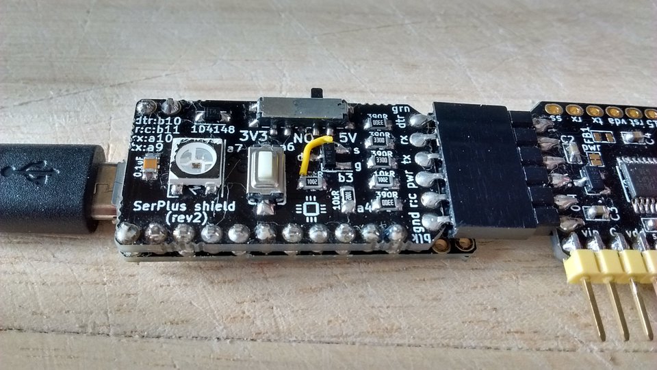
I've made a shield for the bat board (a "batshield") to turn into an F072-based SerPlus, with some extra features: "raw" mode (works as any other USB-to-Serial with DTR), neopixel for status, FET to control output power, slide switch to select 3.3V adn 5V).
jcw's SerPlus is a variation on the classic USB-to-Serial converter, which is designed to work with JeeLabs' jeenode zero and folie. The problem (to which SerPlus is a solution) is that in addition to TX/RX one would like to control MCU's reset and BOOT0 (for easy resetting and uploading firmware), and it's tricky to do it using DTR+RTS signals in a cross-platform way. The SerPlus firmware controls the two pins using the telnet protocol. jcw explained this and made an F103-based board for it, as documented here.
I've ported jcw's F103 firmware to F072, and added some "features" assuming that it will run on [the bat board] with this serplus shield:
- button controlled mode: either "SerPlus mode" or straight "raw UART with DTR"
- slide switch to select 3V3/5V output power
- WS2812 neopixel status LED
- control on/off output power with a FET
- measure output power level using ADC
In the "raw" mode, it works as any other USB-to-serial converter (with DTR), so it can be used to upload firmware to arduino-type boards (tested).
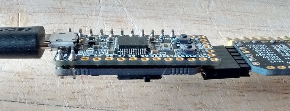
In the photos the serplus shield is quite roughed-up: it's rev2 which had a couple of mistakes (one of them was corrected with the yellow wire). These are fixed on rev3.
Hardware docs
The PCBs can be ordered from pcbs.io. The kicad design files and png schematic are also available.
In principle the PCB can be used without any components (in the same way as jcw's perfboard for the F103 blue pill), just the footprints for the resistors R3, R4, R5 and R6 (marked 390R) need to be bridged - these are just current limiters on the signal lines.
Output power: by default no components are needed, and the output pwr pin is directly connected to the 5V net from USB.
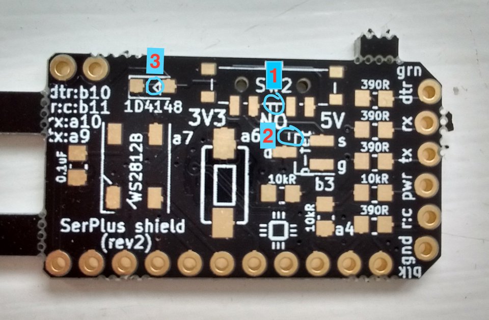
If a 3V3/5V slide switch is desired, cut a trace (physically halfway between the two middle pads of the slide switch, marked 1 on the pic below) and fit the switch. A three-way switch is expected, with the middle position making pwr not connected to anything (useful if the target board has its own power source). The footprint accepts for instance this one.
If a power on/off P-FET is desired (to control power by a MCU pin), cut the trace between the two right-hand pads of the FET footprint (marked 2 on the pic below), solder a P-FET (e.g. this one, but any SOT-23 packaged P-FET with this pinout should be OK) and solder an (approx) 10kOhm R7 resistor - it's the one marked 10kR next to the FET. Once this is done, the connection to pwr can be cut by pulling PB3 pin low.
Another optional component is a WS2812 NeoPixel, 5050 package (I've actually used SK6812). Optionally one can use a 1N4148 diode to lower its power supply voltage (this trick is described here), but remember to cut the trace underneath the diode (marked 3 below)! The data pin is routed to PA7.
The pushbutton is between PA6 and ground, so the expectation is to use the internal pull-up.
The final feature is a voltage divider on the pwr pin routed to PA4 (ADC_IN4). For this, mount two resistors R1 and R2 (marked 10kR on the board - one of them is among the "column" of resistors next to the 6 "UART" pins, and the other one is the 10kR perpendicular to these). This allows for monitoring the voltage on pwr using the analog-to-digital converter in the MCU.