USB stick with attiny85
About a year ago, I made a sort of a DigiSpark, or LittleWire clone on a stripboard. I've come back to it now and made a couple of shields.
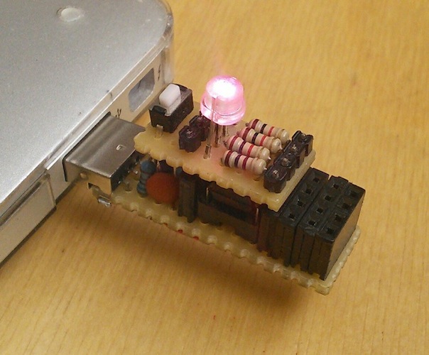
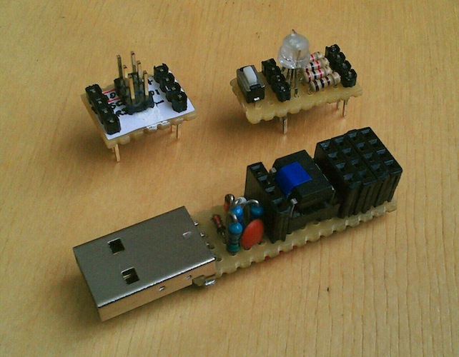
All the pins are brought out to female headers and it has a very small "breadboard" area, so that I can test small parts right away (see pictures below). It is also easy to make "shields" from a piece of a protoboard: I've made a "RGB LED with a button" and a "LittleWire/ICSP header" ones.
I've flashed it with micronucleus bootloader (the same as is used on a DigiSpark), which makes it very easy to switch firmware even with the reset disabled (through fuses).
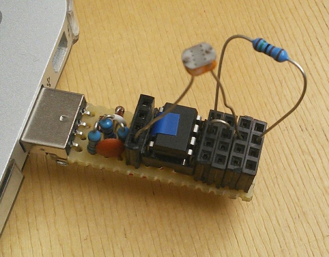
LittleWire firmware makes it exceptionally easy to use it as an AVR ISP programmer (with the ISP shield), or for testing I2C or analog sensors (picture below with a photoresistor). Especially with Bluebie's littlewire.rb ruby bindings.
The piece of tape on top of the attiny is a trick I've learned from vusbtiny on a breadboard: you can flash firmware to attiny45/85 chips by just sticking them on top of the attiny in the stick --- letting them "ride" the programmer. The tape prevents the connection of the two pins that communicate with the computer.
How to make one yourself
Parts
- A piece of a stripboard (4x14 holes, with strips along the long side; it is useful to have it ``wider'', up to the next holes, which allows for soldering the side pins of the USB connector to the side of the board, so that it holds more securely).
- 5 4x1 female PCB headers (or 1 4x1 and 1 4x4). Or just 2 4x1's if you don't want the "breadboard" area.
- ATtiny85 (45 would also work, but after the bootloader you'll have only 2k programming space and e.g. the LittleWire won't fit).
- DIL 8pin IC socket (if you don't want to solder the attiny).
- 2 68Ohm resistors.
- 1 1.5kOhm resistor.
- 2 3V6 Zener diodes.
- 1 0.1uF capacitor.
- USB male type A connector.
- A bit of wire.
Layout

Notes
- The strips run horizontally, and the strips need to be cut between holes (careful!) along three vertical lines (indicated with gray 'x's).
- The resistors, zeners and the cap often share holes, so make sure you've placed all the parts you need before soldering a hole.
- The area is pretty cramped, so almost all parts will need to be vertical (except one zener). It is also good to put a bit of isolation stripped from a wire on the longer resistor legs, so that they won't short when they touch (which they will, since the area is very small).
- Zeners are directional; the strip on one end of a zener is supposed to be away from ground.
- Two extra connections are made on the bottom side with wires, indicated with green in the diagram.
- It is useful to solder the side pins on the USB connector to the side of the board, but for that it needs to be wide enough: what worked for me was to have the board cut through the adjoining holes.
Schematic
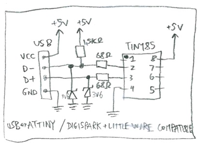
Note that it is compatible with DigiSpark and LittleWire (D- (the one with a pullup) is connected to pin 2/PB3 and D+ is connected to pin 3/PB4), but not with vusbmicro or vusbtiny on a breadboard: those have the signals reversed (D- to pin 3/PB4 and D+ to pin 2/PB3).
Firmware
Get some version of the micronucleus bootloader firmware from here (the standard one is fine) and flash it to your attiny85 --- you'll need an AVR ISP programmer for that. If you have a spare Arduino, you can use it as a programmer, see e.g. here.
Flash the bootloader with (adjust according to your setup, it should be on one line!)
avrdude -c arduino -p attiny85 -b 19200 -P /dev/tty.arduino_tty -U flash:w:micronucleus.hex
Set the fuses.
avrdude -c arduino -p attiny85 -b 19200 -P /dev/tty.arduino_tty -U lfuse:w:0xe1:m -U efuse:w:0xfe:m -U hfuse:w:0xdd:m
(Option: disable reset: this means that you can use PB5/pin 1 as a normal pin, but also that you can no longer program the attiny with an ISP, only through micronucleus. I think DigiSpark ships like this by default. If you screw up, you can try to reset the fuses with some High Voltage Serial Programmer (you can use an Arduino even for this: ScratchMonkey, but you'll need some extra parts). So, if you want to do this, use -U hfuse:w:5d:m instead of the hfuse part above.)
Now the attiny is programmable via micronucleus, so you'll need to get a micronucleus command line program for flashing from here, or build it manually, sources here.
So just pop the programmed attiny into the socket, and you're good to go! A good start for experimenting is the LittleWire firmware, so head over here, get a LittleWire firmware and flash it with
micronucleus --run LittleWire_v13.hex
Have fun!