(Another) FT231X USB-to-serial
I already have so many USB-to-serial boards... but of course I had to try to make another one myself. I went for FT231XS chip, and tried to pack in all the features I ever wanted: selectable 5V/3.3V/no supply; proper 3.3V regulator, limiting i/o levels to 3.5V max but down to whatever the target has, compact layout.
The main motivation was that I wanted a small flat board that I could have on me all the time, with selectable and beefy 5V/3.3V supply. All the USB-to-serial breakouts that I could find could do some of these, but usually not all at the same time. Small usually implies that the supply and level selection are with solder jumpers, or with pin jumpers. 5V supply often implies 5V i/o levels (not good for jeenodes or the ARM boards I was playing with recently, like jeenode zero).
Apart from FTDI chips, there are of course SI labs' CP2102 and CP2104. These are quite good, but only QFN packages, so I couldn't quite use them. Then the Chinese CH340G (crystal, i/o level = supply, ...)
The two that come real close to what I wanted are BUB II, BUB III and Sparkfun FT231X breakout. (Each has a couple of deficiencies: BUB II has USB mini, is not small enough and has pin jumpers, doesn't route out RTS. BUB III doesn't have a regulator and has solder jumpers, likewise Sparkfun's.)
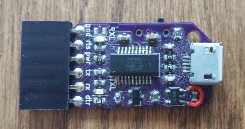
(The photo is of rev1. On that one there is a missing trace between two regulator pads, hence the wire fix. Rev2 (on OSH Park) has that fixed. Also rev2 has the solder jumper to select what's on pin5 of the FTDI connector; rev1 doesn't, it goes directly to RTS - I wanted to disconnect that, and that's the missing resistor. Finally, the board is quite messy - that's the result of actually carrying it around a lot :)
Anyway, FT231XS is not that expensive, and it is very capable and reliable. So, this is the list of features I hopefully manage:
- "Classic" (by now) 6 pin FTDI header, with DTR and RTS routed out (there is a solder jumper that can select between RTS|nothing|CBUS0 pin).
- Proper 3.3V voltage regulator (AP2112K-3.3 600mA).
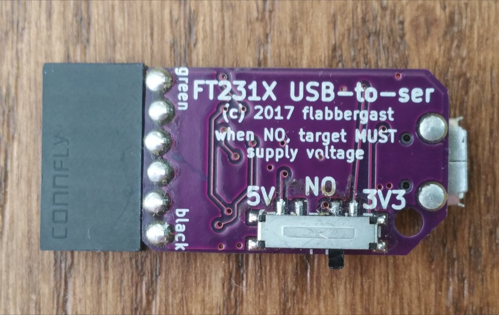
- 3-position slide switch on the side of PCB, to select between supplying 5V, or 3.3V, or nothing.
- I/O level are tied to the target power pin, so they operate on whatever voltage the target board has; I've tried to limit the levels to max 3.3V. Didn't quite succeed here; there is a Schottky and a voltage divider and the upper limit is something like 3.55V (with 5V on power pin). Downwards it operates to FT231XS limit, so 1.8V.
- A whole bunch of current limiting resistors on various lines.
- TX/RX LEDs.
- The PCB isn't marked (almost at all) - it's small and I've only made it for myself (you'll probably need to open the kicad design to see what's what).
In any case, you can order PCBs from OSH Park. The whole design is open: kicad sources and schematic (png).
BOM
- FT231XS (SSOP package)
- AP2112K-3.3 (SOT-23-5 package)
- Schottky diode (SOT-23 ANK package)
- 2x LEDs (0603)
- 2x 27 Ohm resistors (0603)
- 6x 390 Ohm resistors (0603)
- 2x 1000 Ohm resistors (0603)
- 2x 10uF capacitors (0603)
- 2x 0.1uF capacitors (0603)
- 2x 47pF capacitors (0603)
- USB micro B socket (SMT with 2 through holes)
- 3 position slide switch
See the schematic, some of them can be omitted: e.g. just bridge the current limiting resistors on the lines, or just ignore the Schottky (then the i/o levels will go up to the supply current).
(This was actually all done one and a half years ago, late 2017, but I'm only now catching on some of the write-ups.)

