A bit of through-hole fun (with MSP430), part II
Second installment of adventures in MSP430. A Hammond-boxed MSP430G2553-powered sensor board, with RFM69 radio, intended for running mecrisp forth.
Once I found out that mecrisp forth (the lowpower version for MSP430G2553) runs forth prompt consuming only 1.5-2uA almost without any effort, I couldn't resist and had to design a "sensor board" for it.
By "sensor board", I mean a simple board that's supposed to be battery-powered, minimal extra components, have a radio (RFM69 of course), fit well into a "deployable" box, and make it as easy as possible to add some sensor(s).
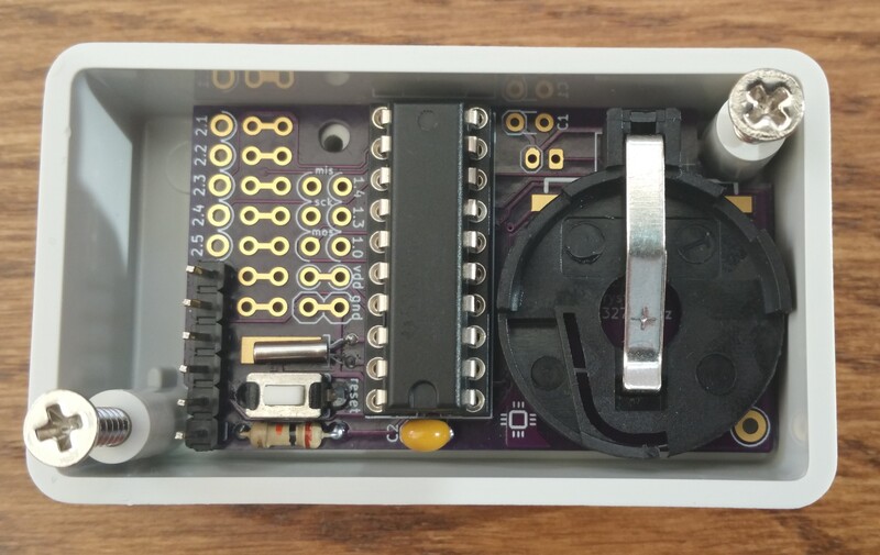
This is the result.
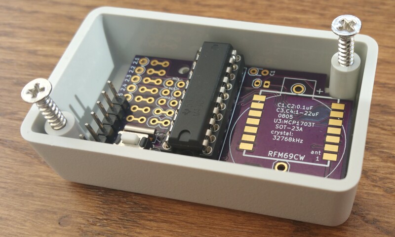
The box is Hammond 1551 HGY (60x35x20mm), so one can reliably and repeatably (hopefully) get the correct box. The PCB can be fixed inside with one or two screws - if the CR2032 holder is mounted, it obscures one of the mounting holes. I couldn't figure out a way to have both holes accessible and fit everything in. Also note that HBK box is also fine - the last two letters denote the colour of the box.
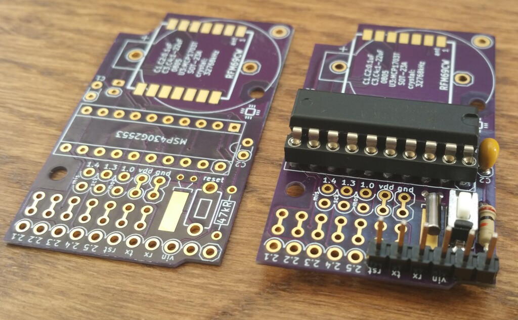
The circuit is really minimal and one can get going with just through-hole components (marked on the PCB):
- 0.1uF filtering cap (or two)
- pull-up resistor on RESET (47kOhm)
- pushbutton for RESET
- 6 pin "FTDI" header (more on this below)
The extras are:
- footprint for a radial 32768kHz crystal (quartz) - this is necessary for low power operation
- footprint for RFM69CW radio with a wire whip antenna
- footprint for a CR2032 battery holder
- footprint for a 2mm JST connector (meant for stuff like LiPo batteries)
- SOT-23A footprint for MCP1703 voltage regulator with 2 (0603) stabilising caps (SMT, but hand-solderable)
- a bunch of solder jumpers (see below)
About power: as usual (for my recent boards) there are two power nets, vin and vdd.
The MCU and the radio are powered from vdd. There is a solder jumper to connect
vin with vdd; then there is just one voltage level throughout the board.
However this limits the supply to about 3.6V max (so 2 AA batteries or a CR2032).
The MCP1703T voltage regulator should take only about 0.5uA when the rest of
the board is "sleepy" (but testing doesn't really support this: when the board
takes about 2-3uA, the regulator seems to want another about 7-10uA - I'll need
to try to figure out what's going on; or maybe try with MSP1700?). So, if
present, vin can be connected to the regulator input instead (solder jumper),
and vdd then to regulator output.
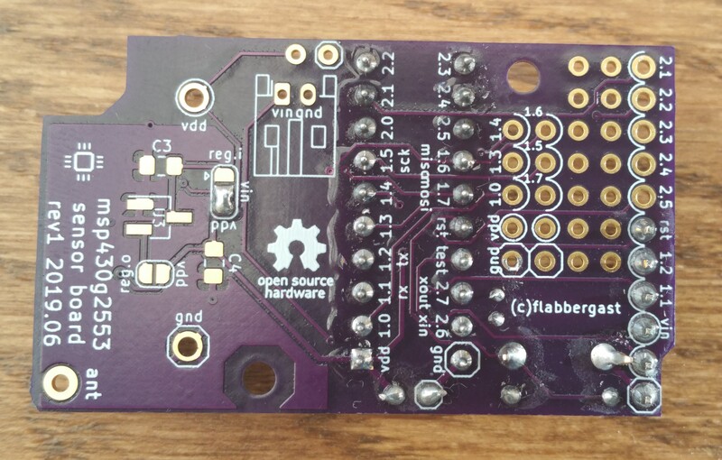
All the MSP430G2553 pins are routed out to through-hole pads (except P2.0 which
is routed to RFM69 CS). There is also a (very) little "prototyping area",
meaning pairs of pads not connected to anything.
The 6-pins that can be used for a "FTDI-like" connector have the "FTDI" layout,
with reset on one side, and with TEST pin on the remaining pin (which usually
doesn't have a special function). These are enough to program the chip (using
e.g. the programmer third of any MSP430 Launchpad and mspdebug).
The expectation is that this is done only once, to flash mecrisp. Subsequently
it's "just" forth programming. I have some words here; most of
it is from mecrisp itself, some of it heavily influenced by Jean-Claude Wippler's
embello.
The flash and RAM size are quite limiting, so it is easier to develop on bigger chips and then extract minimal words for deployment on g2553 - I tend to use mecrisp stellaris on something like jeenode zero or my own weaker variants L0x1 dev board, L0x1 sensor board.
Links
- PCB orderable from OSH Park. (I recommend getting the 0.8mm PCBs, they are really cool and leave more space in the box ;)
- Schematic and kicad sources.
- Some forth words here.
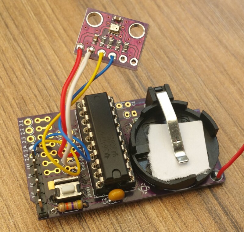
Finally, a photo of the board with the radio, battery socket, and a BMP280 sensor wired to it. Does run on about 2uA in sleep. The forth code for it begins here.