Hammond-boxed sensor board with STM32 L0x1
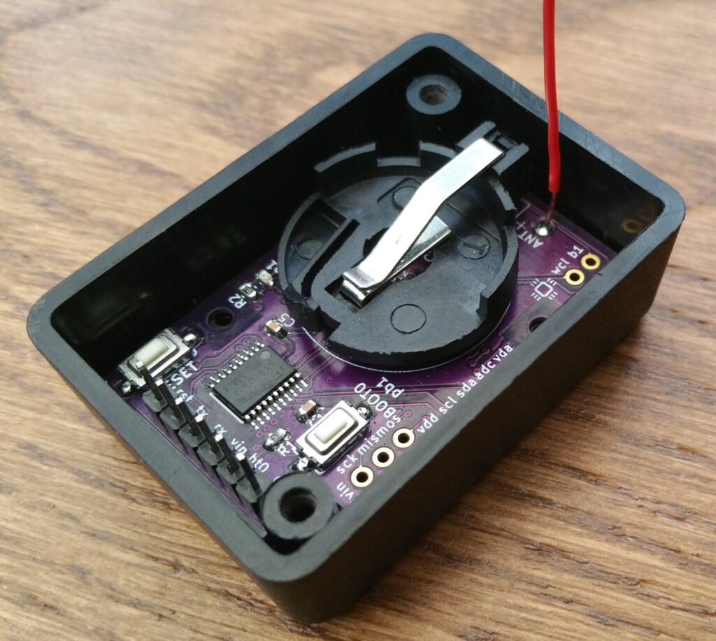
The next step after L0x1 development board: STM32L0x1-based sensor board. Same schematic, but on a PCB which matches Hammond 1551GBK box, with a CR2032 battery holder.
Mechanical
The development board was working satisfactorily, so I decided to try to make an "easily deployable" version. I found that it's tricky for me to find the right "project box" for sensors (usually size, then they don't fit exactly so I need to pad them, then the ebay seller disappears and I can't find another one with the same size...) So this time around I went for one of Hammond boxes: they supply datasheets with exact measurements and drawings of the boxes, they're high quality and not that expensive, and one can reliably buy the correct type. The type used here is 1551G (then two letter indicating the colour, so 1551GBK (black) or 1551GGY (gray)), the outer size is 50x35x20mm. The PCB fits perfectly inside, and can be attached through the two mounting holes.
Hardware
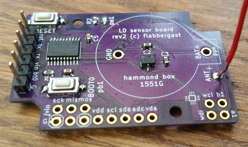
It's based on essentially the same schematic as the development board, with a few more power options. I'll describe the various components of the design separately:
- The MCU gets power from the
vddnet. There is alsovinnet, which either supplies the voltage regulator, or is connected tovdd(jumper). - All the passive components have 0603 footprint.
- The absolute minimum for the board to work, one needs the MCU, a filtering
capacitor
C1(0.1uF) and the pull-down resistor on BOOTR1(10kOhm). And perhaps a 6 pin header to talk to the chip. In this case the power needs to be supplied directly tovddnet, 3.6V maximum. The MCU footprint is TSSOP-20, and expects something pin compatible to STM32L031F6P6 (so L041, or F030, or F042 will all work, although the 'F's are not so good with power consumption). - To get a cleaner analogue supply (
vdda), one can fit a ferrite bead (FB1) and more filtering caps:C41uF, andC50.1uF. When doing this, one needs to cut the trace inside the ferrite footprint, connecting the two pads. - To get a LED, fit the
R2resistor (around 1kOhm) and thepa1LED itself. - To get buttons for RESET and BOOT, just fit them.
- So far there was nothing about power, with the expectation is that the board
will be powered directly to the
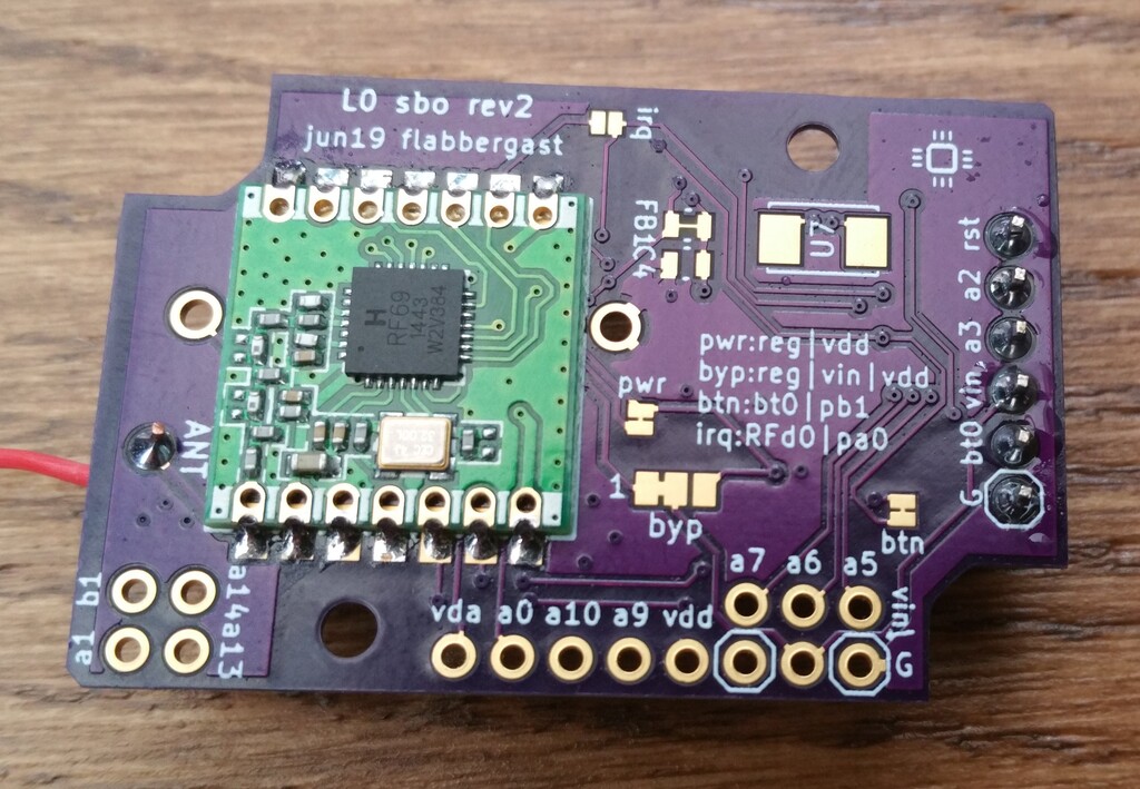
vddnet. In this case it may be desirable to connect thevinnet tovddusing the 3-positionbypsolder jumper, so that the correct voltage shows up on thevinpin of the 6pin FTDI header, so that the FTDI adaptor can adjust the levels on tx/rx/reset pins and doesn't try to overpower the battery. (Or, removing the battery, then can power the board with the FTDI adaptor supplying up to 3.3V.) In this case I would also recommend disconnecting the power circuit from the rest of the board completely, i.e. disconnecting the other side of the 3-positionbypjumper, and disconnecting thepwrjumper. (Note that some of these are connected with a trace by default, so you may need to cut the traces.) - The other power option is to use the regulator. So fit IC2 with a MCP1703T
regulator (SOT-23A) footprint, preferably 3.3V or 3V, and the stabilising caps
C2andC3, at least 2.2uF each (can be higher, say 10uF). Connect thepwrjumper, connect one side ofbypjumper (regtovin) and disconnect the other side (vintovdd). Then can use any of thevinpads to supply, the regulated output will power the MCU. For example, one can fit a JST socket on the bottom side of the board into thevinandgndholes that are next to each other, and supply the system from a LiPo battery. - There is a footprint for a potential crystal (
U7) connected to the correct pins on the MCU; but I didn't put in any loading caps footprints. So be careful. - Finally, the radio. The footprint is for RFM69CW; a hole for a wire whip antenna,
and one can connect the
PA0with theIRQpin on the radio with theirqsolder jumper. - The through-hole pads are marked, with their function on one side, and with
PAxon the other side of the PCB. - The 6pin "FTDI" header has the usual pinout, so that it can be used with a garden variety USB-to-serial board, or better, with SerPlus (which can also take care of uploading firmware).
You can get PCBs from OSH Park - I recommend going for the 0.8mm thick ones: they're very cool, and there's more space in the box :)
Firmware
I use mecrisp stellaris. Starting from jcw's embello, I have some forth words here. (Jean-Claude Wippler wrote up about getting the power consumption as low as possible in a blog post. It's for jeenode zero, but applies also for L041.)
UPDATE 2019-07-24: A boxed board with SHT31-D temperature and humidity sensor is now reporting the data from the outside. The forth code is here. It runs on a CR2032 coin cell battery, and takes 2.5uA in sleep. That's pretty sweet; I originally wanted to use 2 AA batteries, but with the consumption this low it's not worth it. I'll see how it holds up.


