Remarks about soldering tinyUSBboard rev4 (SMT) kit
02 December 2014
This post is about soldering matrixstorm's tinyUSBboard rev4 - you can get a kit at Tindie for an incredible price of $4.
If this is your first SMT kit (as it was for me), a good place to start is watching some youtube tutorials on SMT soldering.
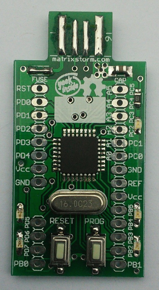
My end result:
Equipment requirements:
- soldering iron (any will do - I only have one with a needlepoint tip, not temperature controlled)
- multimeter (for checking that there are no shorts, and also to check that the place and orientation of parts is OK)
- fine solder (I had 0.5mm)
- liquid flux - this is a must! It is really magic!
- solder wick (for fixing errors - e.g. when you put too much solder somewhere)
Instructions
Note: when I refer to orientation, I'm always assuming the PCB (stick) itself is oriented so that the USB connector is pointing upwards.
- Solder the atmega8(a) IC first. Orientation wasn't clear, so: The 'dot' corner should go to the upper-left corner of the TQFP landing on the PCB. If your atmega8a doesn't have the dot (as mine didn't have), it should have a little triangle printed on the top side. When the triangle points 'up', the imaginary 'dot' is in the upper-left corner. It should be the corner closest to the triangle.
- Then solder all other SMT components on the top side of the PCB:
- 22uF capacitor in the upper-right corner
- 10kOhm resistor in the upper-right corner
- 5 LEDs. These are polarized, so care needs to be taken when orienting them. The LEDs I had had a green triangle on the bottom side: the tip points to GND, the base is on the VCC side. I now list the LEDs in the clockwise order on the PCB, starting in the upper-right corner:
- green LED. GND is the top pad.
- red LED. GND is the top pad.
- red LED (lower-right corner of the PCB). GND is the top pad.
- red LED (this is the one in the lower-left corner of the PCB). GND is the top pad.
- red LED. GND is the bottom pad.
- Solder SMT components on the bottom side of the PCB:
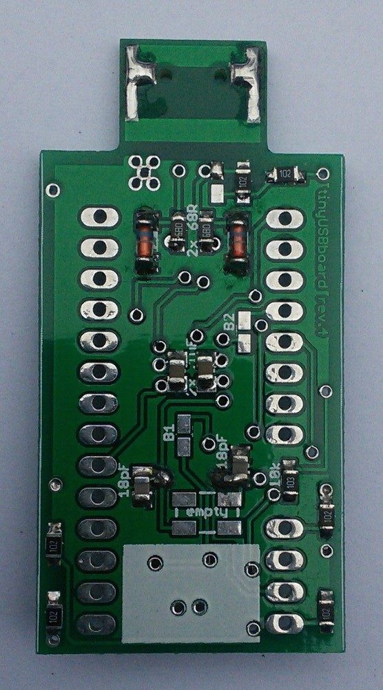
- Capacitors: Two 18pF go to the side of the crystal holes (lower part of the PCB). Two 1uF go close to each other, on the reverse side from atmega8.
- Resistors:
- Two 68Ohm (marked 680) go close to each other, vertically placed, close to pads for zeners.
- Two 1kOhm (marked 102) go close to the USB connector - there are three pairs of pads (two vertical, one horizontal) there; only two are needed (one vertical, doesn't matter which one, and the horizontal one). Just leave one pair of the vertical pads unsoldered (I suppose another 1kOhm resistor should go there if the USB connection turns out flaky).
- Four 1kOhm resistors on the sides of the PCB, close to the lower edge of the PCB (limiting resistors for the LEDs on the top side).
- One 10kOhm resistor (marked 103; pull-up for the reset button). Between the two columns of through-hole pads on the right side of the PCB.
- Zeners. The pads are well marked. These are polarized - the side with the blue ring should go closer to the USB connector.
- Now turn the PCB and solder the two buttons on the top side of the PCB.
- The final part is the crystal. As per Stefan's instructions, leave a bit of space between the crystal and the PCB, don't solder it flush. I inserted two bits of paper between the crystal and the PCB when soldering, and then pulled them out when I was done.
- There's one more "part" to be dealt with, namely the fuse in the top-left corner of the top side of the PCB. This doesn't come in the kit, so if you have a 0805-sized fuse (usually goes under the name Resettable PTC fuse; probably want one with 500mA tripping current) you can solder it there. I just soldered a small piece of wire (actually a piece of the crystal's clipped leg) there. Today's computers usually have USB port fuses built in. In my experience, my computer is much better at dealing with a short situation than any onboard fuse - it just disconnects the shorted USB and I get a message that my USB device was drawing too much current :)
- The last step is to thicken the pads on the USB connector, so that it makes good connection with the USB slots when inserted. If you want to smoothen out the solder on the pads, just put some liquid flux on top and run along the pad with the soldering iron. This should make the solder smooth and shiny.

