USB tester
Inspired by FriedCircuits' USB Tester 2.0, I've decided that instead of ordering one, I'll make one myself on a protoboard.
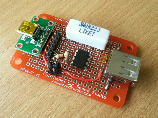
I had one Dangerous Prototypes' 6037 protoboard, which had ideal size for this. I also have an Sick of Beige acrylic cover for it, although the top part of course doesn't fit. (Only after soldering I've realised that I probably have top and bottom reversed...)
So, besides breaking out all the USB pins on the header near the Mini USB connector and breaking the VBUS line onto a jumper (to hook a multimeter into the line to measure current), I wanted to "convert current to voltage", so that I can measure the current with a microcontroller, or a voltmeter, since my basic one can't measure current over 200mA directly.
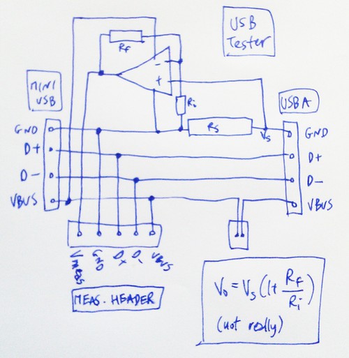
The relevant source for this part of the circuit is Embedded Labs' writeup. Basically, the ground line is connected through a low resistance (and high wattage) resistor, and the voltage drop on this resistor is then amplified using an operational amplifier (non-inverting). I used:
- Rs, the "measuring" resistor, has resistance 0.207R, can dissipate 3W. The voltage drop is V=IR, so max 2 * 0.207 = 0.414 V for max 2A of current, but usually much smaller. The wattage is sufficient: Power = VI = RI^2 = 0.207 * 2^2 = 0.828 W, well below 3W for 2A of current.
- op amp is LM358, with resistors Ri=978R, Rf=9770R, so the amplification is approximately 1+Rf/Ri = 11 times. So for max 2A of current, the resulting voltage is at most (1+Rf/Ri) * 0.414 = 4.55V, which is below the required 5V.
- the final computed Coeff = 2.275 V/A, where I = Vmeasured / Coeff.
Comparing the results using a multimeter for current, and then measuring voltage on the "sense" pin show that the multimeter ones are by about 20mA lower. Why - I have no idea, but I'm sure that someone who actually understands electronics can enlighten me :) My uneducated guess would be that it's because I'm powering the amp circuit with the USB source power.
A table of measured things (minimus m32u2, ciseco URF, gl.inet router) follows. There is some uncertainty, since the consumption of the latter two devices changes over time a bit. For the computation, I've used the "average".
Vmeasured (V)   Imeasured (mA)  Icomputed (mA)
0.111           27.3            49
0.118-0.126     30-33           54
0.338-0.350     128-135         151
So I suppose the final formula to use is Icomputed = Vmeasured / 2.275 - 0.02 A.
Schematic:
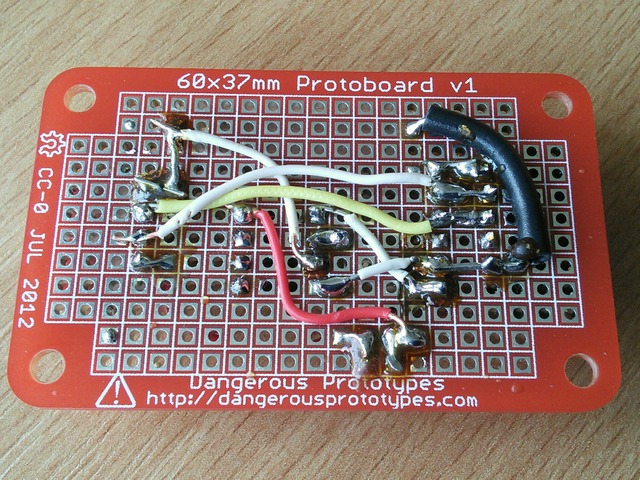
Finally, the "bottom" pic, showing my bad soldering skills and habits: