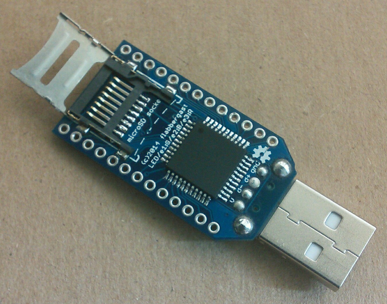
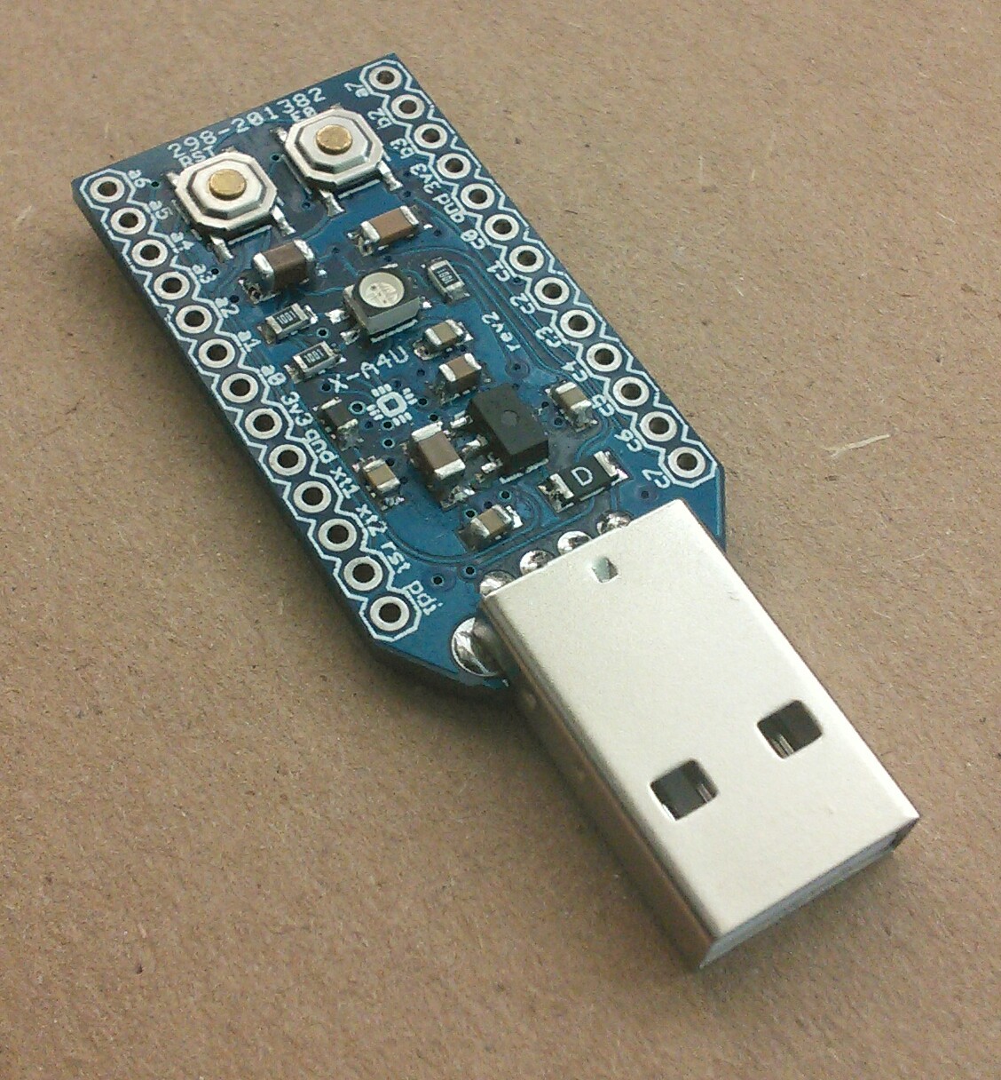
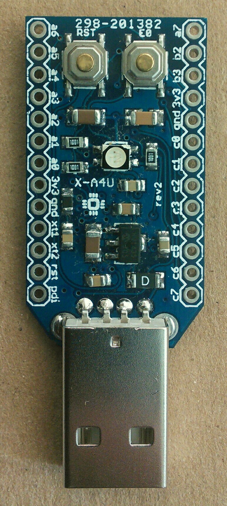
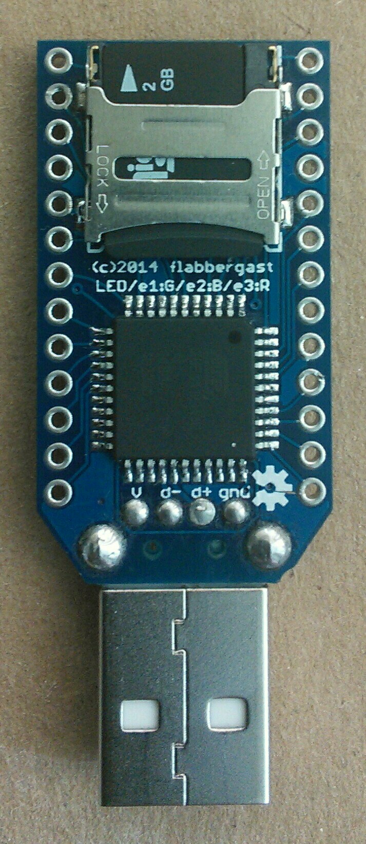
X-A4U-stick rev2
Following up on X-A4U-stick rev1, I've made another revision of the board, again Open Hardware.
NOTE: The content of this post is pretty much the same as the main project page.
Compared to revision 1, there's no EEPROM landing, the two LEDs are replaced by one RGB LED and there's an extra button (routed to RESET). I also replaced Sparkfun's push-push microSD socket by a hinged one from ebay, to lower the cost and make it easier to solder.
The possible usages of this stick that I had in mind when designing it were:
- Use microSD as mass storage, but encrypting the data before writing. An alpha version of firmware is here: enstix. Note that it's relatively slow (I was getting about 130kB/sec for reading).
- Use the stick to act as keyboard (+mouse), reading what should be "pressed" from microSD - much like the Rubber Ducky, with an addition of a mouse.
- Use RGB led for a mood light (sample firmware linked below).
Downloads/resources
- EAGLE files are in my public eagle repo.
- Schematic png
- Test firmwares
Features
- ATxmega128A4U: actually any -A4U xmega would work.
- MicroSD socket
- One general pushbutton and RESET pushbutton.
- RGB LED ("standard" SMT 1210).
- A reasonable (?) amount of xmega's pins routed out to through-hole pads with standard spacing - so potentially usable on a breadboard, or with a homemade "shields" from a piece of protoboard. The PDI programming interface and crystal/oscillator pins are also brought out. (The layout matches the revision1 board.)
- Bootloaded with DFU bootloader.
Usage notes
The atxmega is bootloaded with ATMEL's DFU bootloader, which is entered by pressing the E0 button during power-up or reset. So to program the stick, enter the bootloader mode, the stick should enumerate as ATMEL DFU device (this needs a driver on Windows), and then either use ATMEL's FLIP utility, or the open source dfu-programmer.
The button is wired to PE0, the RGB LED to PE1 (green), PE2 (red) and PE3 (blue). (Note there's a mistake on the silkscreen, red and blue are switched.)
The voltage regulator is rated to 250mA, same as the PTC fuse. However it's SOT-89 package, so the heat dissipation provided by the package might not be sufficient when one gets close to the rating.
In the current revision there's no way to bypass the voltage regulator (and power the board by wiring regulated 3.3V to one of the pads), so the board is not really suitable for very low power applications. It's meant to be used as a USB stick.
The analog supply voltage pin (AVCC) is connected to the supply through a ferrite bead, as per ATMEL's recommendation, so the analog output (DAC0/1) and analog input should be relatively clean - but I don't have an oscilloscope to verify this.
Some of the technical points from revision1 apply also here:
- The microSD SPI interface is also to
PORTC, with the exception of the chip select pin. This means that/SSpin fromPORTCcan be used for any external SPI chip, and also that the xmega can act as SPI slave. One warning though: when using the hardware SPI (e.g. for microSD), the/SSpin onPORTC(namelyPC4) should not be an input andLOW- this hangs the usual SPI code. So, even thoughPC4is not used for talking to microSD, it needs to be an output, or tiedHIGH.